

Deployment setup is for adding your device to the project and locating it on the map.
If you encounter problems during setup and calibration process, there is a troubleshooting guide at the end of these instructions.
Device Detail (Step 1)
Give a name to the device based on the location and the kind of device. It is optional to give a description. The user will need to input Device Model type, the Serial number, and also to specify the device type (PTZ or others). Only IP capable cameras can work with DCM. A fully analogue security camera, that has no option to save a stream in an IP accessible location cannot be used.
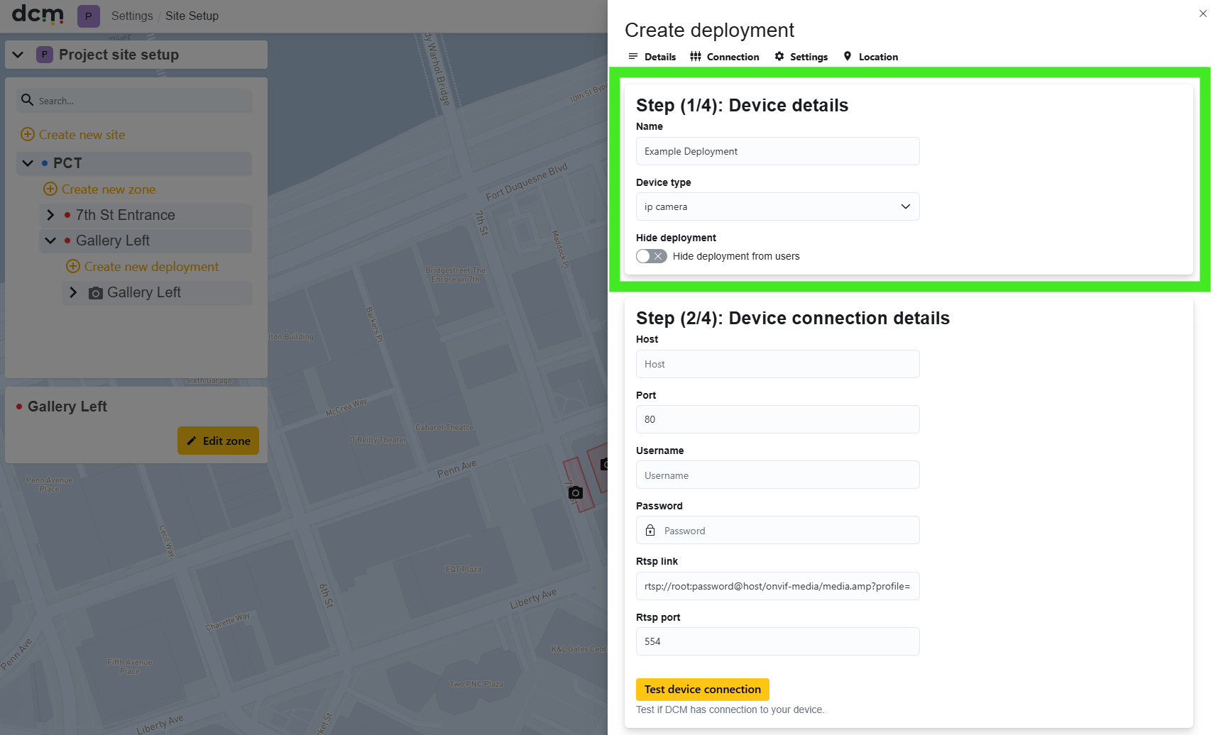
Device Type: There are two main options.
-
PTZ
PTZ cameras, are cameras that allow users to move the camera view. They have some options unavailable for fixed cameras, such as configuring multiple scenes (each with its own calibration) or compensating for a long viewing distance using a mode that moves the view in a cycle, starting from a wide view then zooming into a specific area to collect better mood data.
In this mode, the driver will detect if a user is manually moving the PTZ function, and pause data collection. Data collection must be manually restarted by “unpausing” the camera on the DCM dash to resume data collection in this mode. -
IP Camera
If your camera has a fixed view, is a PTZ camera that you do not intend to move, or is any other form of analogue camera that saves its video stream to an IP accessible location, choose this option.
This is actually the simplest option even if your camera is PTZ capable, but you intend to collect data from a single calibrated area, as it never requires manual intervention. The trad-off however, is that in this mode the driver will not detect if a PTZ capable camera has been moved away from the calibrated original DCM home position. Be aware, that any time the camera is not in the originally calibrated home position, data will be inaccurate.
Device connection Detail (Step 2)
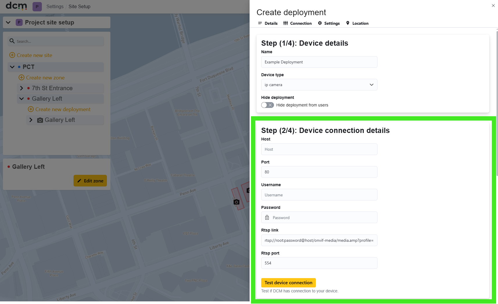
Enter the specific IP address of the camera or stream. The camera must comply with the ONVIF standard (the vast majority of modern cameras at least comply with the basics of this).
We also need access details for the camera to be used, including RTSP link. This can usually be obtained from the Video Management System (VMS) for the specific camera, or alternatively using ONVIF Device manager software: https://sourceforge.net/projects/onvifdm/
The user credentials you supply will need to have at least operator level access to the camera. For the option of full PTZ control, the user needs to be an ONVIF compatible user with admin or operator level access. Most IP cameras support this standard with their default users. A few camera brands however, require ONVIF users to be created separately. If your camera software has a separate ONVIF user account list, you may need to create an ONVIF user to use with DCM.
In most cases, no alteration to the camera settings in the VMS will be necessary. However, if you have any settings that tightly restrict connections, these may need to be adjusted. See the troubleshooting guide at the end of this section for more information.
A resolution of at least 1080p is recommended. Lower resolution cameras may work with reduced detection accuracy and range.
The “Test device connection” button can be used to verify the camera is capable of connecting to DCM.
If this fails, consult the troubleshooting guide at the end of this section.
-
Input the ONVIF username and password for the camera and click Test device connection to make sure data input is correct.
-
If you are unable to get a success message from this test please ensure that the details you have entered are correct and the camera stream can be viewed using its native VMS.
Deployment settings (Step 3)
This section is mainly for setting operation times
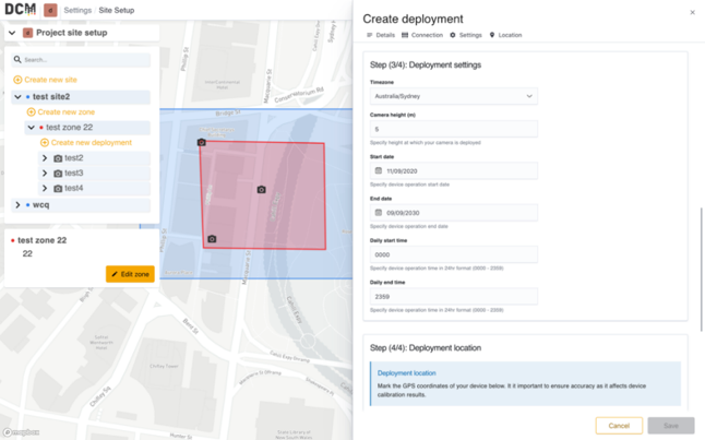
The time zone and start/end date will default to the dates set in the project setup screen. Operational time will default to 24 hr operation. Optionally the user can restrict operational dates and times further on a camera by camera basis here.
If a more restrictive start and end time is defined, the feed from this camera will be unavailable outside these times.
Note that these camera specific settings are over-ridden if a project wide schedule is defined and enabled in the Project Setup screens. If an active schedule exists, ALL project cameras will follow that, instead of the settings in this section. If the project schedule is disabled, the cameras will revert to using the operational times set here.
Deployment location (Step 4)
Locate the camera by placing it on the map within the zone area. The camera’s location does not need to be in the Zone, the location can be an approximation but the closer you are the better the results in the next steps.
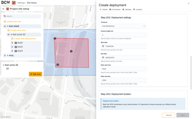
The position can be defined on the map, or by entering latitude and longitude co-ordinates directly.
For outside installations, a satellite overlay is available to assist with placement.